Desoldering the 18650 holders for a custom cell pack
CRANK's 6 × 18650 plan: strip the holders off the battery board, wire two banks of three cells in parallel through bus bars, and house them in a printed back.
What it takes
- Disassembly
- Soldering
- 3D print
- Purchase required
Difficulty 3 of 3 - advanced.
Details
Two threads from May 2024. The wiring one settles what the battery board actually is: J1/J2 are paralleled, D1/D2 are polarity-protection diodes, F1/F2 are PTC fuses, and the AXP228 is a single-cell charger with a 480-minute time cut-off, so paralleled cells need no balancing but must be identical and pre-charged to the same level - Krim's view is that six mixed cells are asking for trouble and a pack with its own protection is safer. CRANK settled on six matching cells charged externally before testing. The desoldering thread is the practical part: the holder joints sit on a large ground plane and would not wick at up to 357 °C, and the advice that worked was a big-tipped iron at around 450 °C, a well-tinned tip, low-temperature solder as a heat bridge and braid to remove the bulk.
The finished six-cell console was never posted, so treat the pack as a plan and the desoldering advice as the useful part.
Links
Open at Forum threadRelated mods
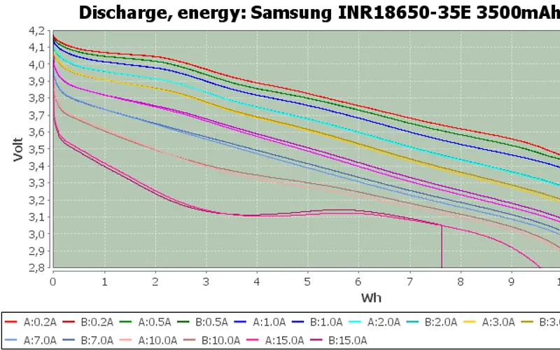
Any genuine branded 3,000–3,500 mAh 18650 works, flat-top or button-top; listings claiming much more than 3,500 mAh are fakes.
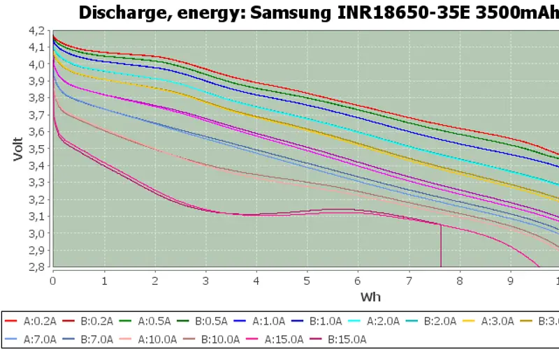
hotellonely's Python script logs the PMIC's voltage and current every 0.1 s until the console dies, giving a real watt-hour figure for any cell or pack.
Swap the two 18650s for a single 10,000 mAh 9858102 pouch - 24–31 Wh measured - but only with a protection board that survives the uConsole's 5 A peaks.
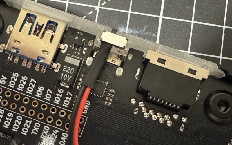
beams' MSK12C02 slide switch uses the pads HackerGadgets reserved on the NVMe battery board to cut the cells - and the NVMe - without a hole in the case.
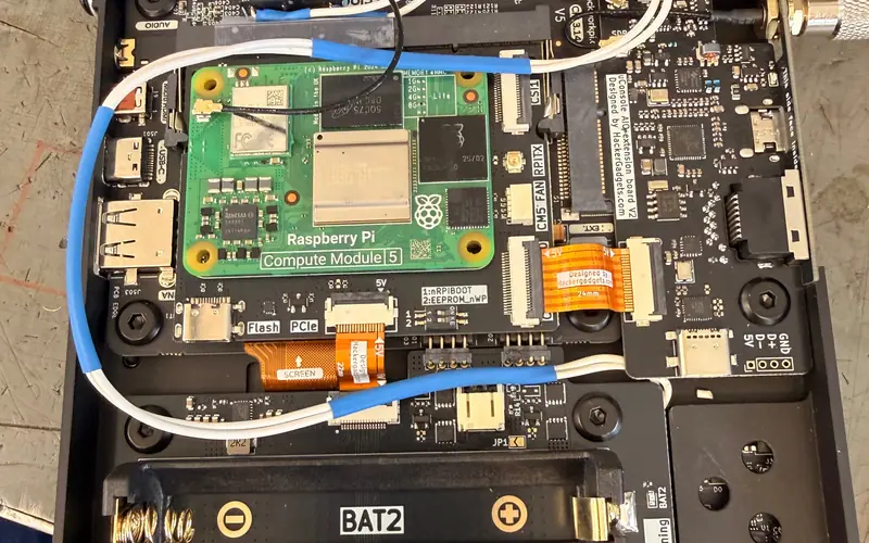
A Crouzet 83170.4 microswitch on the battery board's J6 pads, reached through the rear antenna hole, gives a CM5 a reset button without drilling.
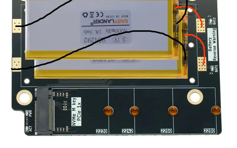
Stack two 5 Ah pouches where the 18650s were and wire them in parallel to the battery board for about 31–33 Wh - after charging both to the same level.